Generating Color Video
How the colorburst was wrangled
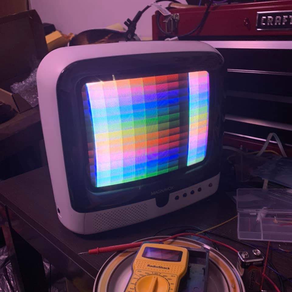
Getting a bunch of logic chips on a breadboard to put a picture on a TV already felt like a major accomplishment. Even if the image was in black and white. However, I thus far had the benefit of reading and adapting the Pong schematic. The puzzle of producing color would be a bit more open-ended. This is probably the part of the project that I learned the most from, reading not only about different ways to encode data in a signal but also about the history of television technology.
How composite works
The design of composite video was strongly influenced by the desire to be backwards-compatible with existing black-and-white video equipment. After all, it would be harder to sell TV studios on broadcasting in color if they'd lose their viewer base of black-and-white TV owners. The color information needed to be superimposed on a monochrome signal without disturbing the image. The chosen solution would be to add a carrier wave at a higher frequency, which could be filtered out by black-and-white TVs but interpreted as color by a color TV. This color signal, a 3.579MHz sine wave, would be modulated in both its amplitude and phase.
Because this was the key part I hadn't previously understood, I'll go into a little more detail as to what is meant by "phase" here. At the beginning of every line in the image, a short burst of the 3.579MHz sine wave would be transmitted just after the horizontal sync pulse but before the image-bearing portion of the signal. This burst would be used as a reference by which to compare the color signal present in the picture. Hence the term "colorburst".
A color television receiving the signal would filter out the lower-frequency brightness-encoding "luminance" signal, and compare the resulting "chrominance" signal against the initial colorburst. The relative amplitude of the chrominance would determine how saturated the color would be. A lower amplitude would produced a more washed-out color, and if the amplitude was zero such as on a black-and-white transmission, the result would simply be a shade of gray.To determine the hue, in other words which fundamental color of the rainbow is being applied, the chrominance signal is measured for how delayed its sine wave is compared to the colorburst. This delay is called phase, and is measured in degrees because it is actually circular. What I mean here is that if the sine wave is delayed enough that the peak of one cycle is simultaneous with the peak of the carrier's next cycle, that is indistinguishable from not being delayed at all! So we can define this delay as a measure from 0 to 360 degrees. It is this measure that determines whether the color of a given part of the output image is red, orange, yellow, green, blue, or violet.
Therefore, in order to add color to my video signal, all I needed to do was produce a 3.579Mhz wave over which I could execute digital control of its phase and amplitude. How hard could it be?
How hard it ended up being
As it turned out there are a few ways to go about this; with varying degrees of precision, cost, and reliability. Hobbyists building TTL color display adapters for their computers in the olden days might use inverters or buffers to introduce a delay from the logic gates. Then an analog multiplexer could be used to select differing levels of delay by branching off a chain of buffers at different places along the chain. This makes for an effective and cheap way of producing different phases of the signal, and is described in Don Lancaster's TV Typewriter Cookbook.
This method has a couple of properties that worried me, though. One is that modern logic gate ICs have shorter delay times than the ones available in 1976. Another is that these delays aren't specified exactly, and can vary with voltage, temperature or even which manufacturer produced the chip. Rather than force a prospective Gametank builder to choose a very specific buffer or inverter of uncertain availability, I wanted a solution that would be rooted in the boolean logic of the circuit design, rather than relying strictly on the physical properties of the implementation.
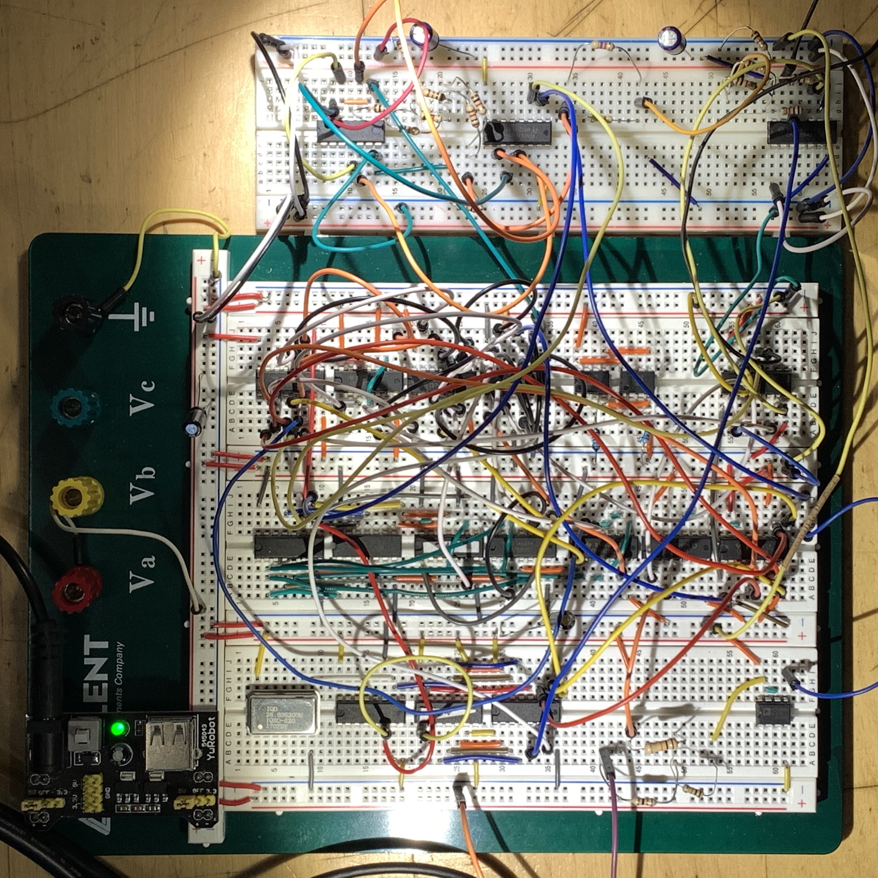
Eventually I'd stumble across documents that referred to a shift register being used in the Nintendo Entertainment System to generate these colorburst phases, though these mentions were nonspecific about how it was arranged. What I did know was that I'd need not only a shift register, but also a clock source that would operate at a higher multiple of the colorburst frequency than I was dealing with. The previous black-and-white prototype used a 14MHz clock, or 4x the colorburst frequency. After sourcing a 28MHz oscillator, I did some breadboard experiements and found that it was relatively straightforward to generate eight distinct phases using this approach.
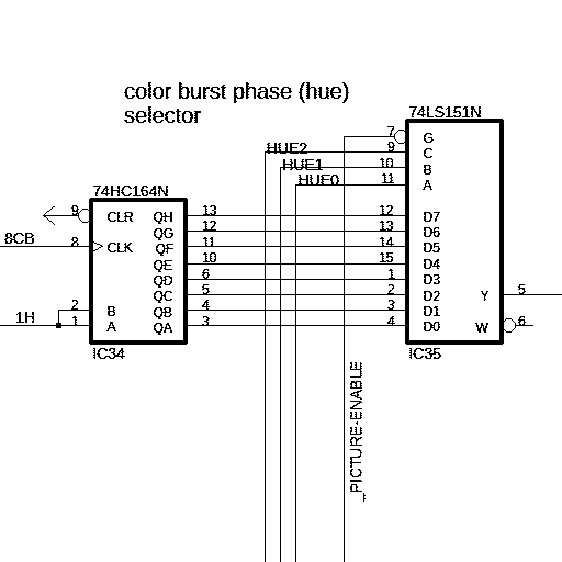
With this handled, the rest was a bit easier. I'd use 2:1 multiplexers controlled by different blanking lines of the video generator, which would gate the input bits to resistor ladder DACs that generated the luminance and chrominance signals. During sync pulses the output would be pulled low. During a short period afterward the DACs would be set to hardwired values for the reference burst. Then, during the rest of each line, the DACs would simply be controlled by the output of the Video RAM chip.
In parallel with studying the mysterious ways of the colorburst, I also had an (admittedly) drawn out process for deciding exactly how the graphics data should correspond to the output color. The previous video prototype was able to pack eight pixels into each byte, since each would only be either black or white. For some time I had considered using an indexed color palette which would let each pixel be one of 16 colors and pack two pixels into each byte. Some nice pictures can be made this way, though there is a complexity cost. Any pixel manipulations from the 8-bit CPU would have to account for the other pixel in each byte. Given that a full screen generally has a great many pixels, any slowdown to a per-pixel operation would be quite apparent.
Ultimately to strike a balance between resolution, complexity, and performance, I opted to design for one pixel per byte. Rather than the approach of using a palette, I'd assign specific bits from each byte to control a particular bit on an output DAC. The color phase (hue) and luminance would each be controlled by three bits, with the remaining two bits controllin color amplitude (saturation).
Another problem I had to figure out was making sure that the output signal had the correct voltage parameters. My black-and-white video prototype actually only worked on specific older CRT televisions, but I wanted to make sure that the Gametank would function with a wider range of televisions that might be more stringent about the composite video standard. Similar to the misadventures with audio mixing, this would require me to break out wires from the video generator PCB onto a breadboard to redo the circuit that mixes the sync, luminance, and chrominance signals.
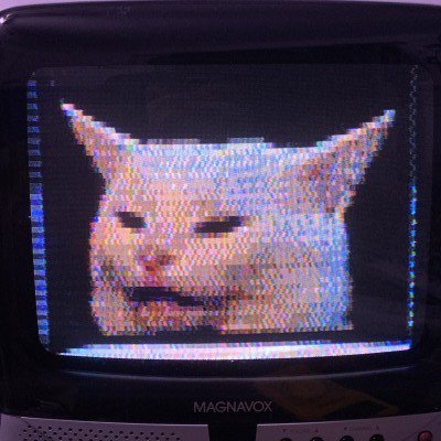
One benefit of this 1 pixel/byte setup that would become apparent later was that image conversion from a bitmap image file would be rather simple. If each byte value correlated to a specific color, I needed only generate a palette file where the color at each index would have the RGB equivalent of the color the video board would output when interpreting that index as a pixel. This palette file can be used in programs such as Photoshop or Aseprite to create a bitmap file that would appear on the computer screen approximately as it would when displayed by the Gametank. This file, with its header bytes deleted, could then be dropped into a ROM binary to be used by the console without any other modification.
For NTSC video: the sync level is expected to be around 0v, the black level around 0.4v, and the brightest part of an image around 1v. The colorburst reference is also expected to have an amplitude around a quarter of the luminance amplitude, and for the sine wave to be centered on the black level. I'm still working on my patience for analog electronics math, so my approach in solving this wasn't particularly sophisticated. I googled for "resistor network calculator" and pretty much just plugged in different resistance values until I arrived at output numbers that looked right. As suggested in TV Typewriter Cookbook I combined the chrominance signal into the mix through a capacitor, which allows the sine wave through but not the base voltage. i.e. the low parts of the sine wave would dip below the black level instead of sitting on top. Because this capacitive coupling works just as well in reverse, it could act as a low pass filter to the luminance and create a smearing effect. However by trying out different capacitor values on the breadboard I was able to settle on a frequency response that included the colorburst but not the smearing.