
Building the SLP
These instructions will show you how to build an SLP with 5 stages. Four of these will be wet stages with tanks, and the fifth is an open-air stage to give the film a chance to lose some moisture before getting spooled onto the takeup reel. This configuration is ideal for a black-and-white negative process with develop, stop, fix, and rinse stages. This page will describe the basic version of the SLP, which does not have a heater and takes about 8 hours to process 100ft. The heat system will be described in the article "Heating Up", and can take this processing time down to a half hour for the same 100ft of film.
Parts/materials
This build uses a combination parts you can buy at your local hardware store, parts you can source inexpensively at any overly-large online retail giant, and parts you can fabricate on an entry-level 3D printer.
A list of purchased materials is available on this Google sheet, but I'll summarize them here as well.
- Steel framing strips (the kind with holes drilled every 3/4")
- 4" Wide by 2ft long PVC pipes, matching flat end-caps, and cement
- PVC bars, 3/8" by 1 1/2" by 3 feet
- 12v motor, speed controller, and some wiring accessories
- Assorted nuts and bolts
Printing the rest...
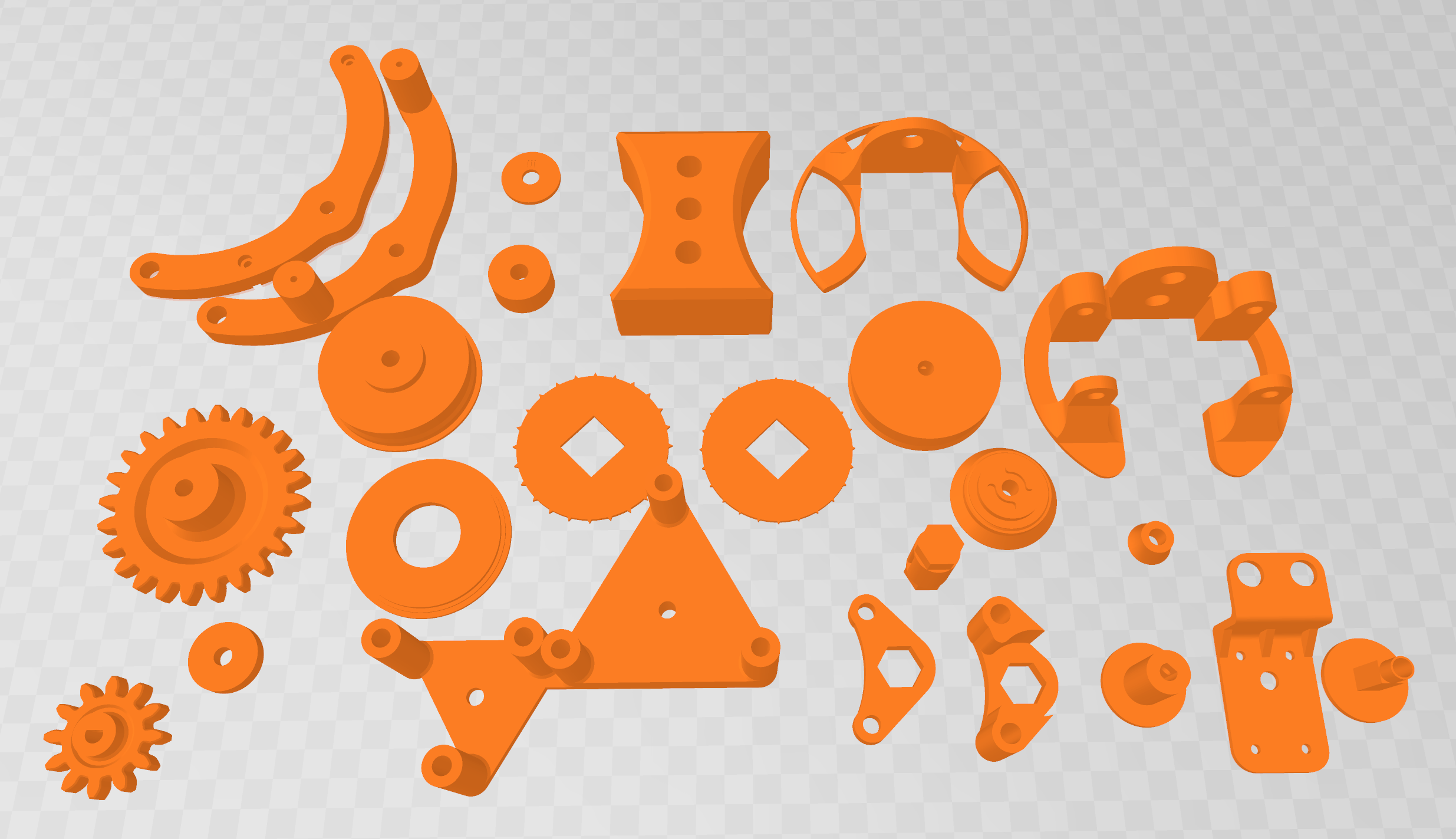
The printed parts include the rollers, the sprocket and associated mechanics for pulling the film, and several structural pieces to keep the rollers centered in the tank and align the overall structure.
For each stage you'll need three rollers (6 halves), one "topmount-pvc", one "spacer-pvc-reinforced", and two "tankspacers".
For the film puller and takeup mechanism you'll need two more rollers, two of "arm-spacer.stl", and one of pretty much everything else. (Admittedly not a great description, I'll try to construct a labelled diagram later)
Assembling the rollers
Because of certain strengths and weaknesses of 3D printing, the rollers each consist of two halves that are glued together. The also will normally come out with their center hole a bit undersized, which we will correct with a power drill.
First you'll need to glue together all the roller halves. I recommend getting a super glue advertized as having a "gel" consistency. Cheap super glues can be extremely runny and suddenly end up in unexpected places no matter how careful you are. At the very least don't wear your favorite clothes and don't do this at a favorite table on your favorite chair.
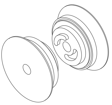
A small amount of glue should be placed in the curved slots of each roller and around the curved alignment pins. Slowly press the two halves together so as not to squirt glue out the sides. Try to use just enough glue to stick the parts together without seeping out the sides, as it's preferable to keep unnecessary materials away from your film.
Give the glued rollers a bit of time to dry, according to the recommendations on the glue packaging. Once they are firmly attached, you can start to drill the center holes to their proper size. This will be done in two stages. You can do this with a common hand held power drill, but I strongly recommend that you do not hold the roller in your bare hand. If the drill bit gets stuck on the roller and the roller starts to spin rapidly, you can get a nasty friction burn faster than you'll think to pull your hand away.
The first stage of drilling should be a 1/4" bit. Make sure to align the direction of the bit as straight as you can with the existing hole, and drill. There shouldn't be a whole lot of resistance, but do take care to pay attention to the sound of your drill and the heat generated by the bit after drilling. If the drill sounds particularly strained or the bit is too hot, there's a risk of getting the bit caught or the plastic being melted instead of cut.
The second stage of drilling requires moving up to a slightly larger drill bit, so that the rollers will spin freely on a 1/4" bolt with little friction. The specific size isn't super important so long as the hole isn't big enough to let the roller rattle excessively, but if you have a set of drill bits you can use whatever is the next size up from 1/4". If you are buying drill bits for this project, you can use a 9/32" bit.
Once you have drilled out all of the rollers (twice!) they're pretty much ready to use and you can move on to the next sections.
Building the tanks
This part of the build has more gluing (actually cement and epoxy, not glue) but no drilling. The goal is to make a watertight tank that can stand on its own, and align with adjacent tanks by simply pressing them together.
For each tank you'll need the two "tankspacers", one pipe, and one end cap. You'll start by cementing the cap onto the end of the pipe and then using epoxy to attach the spacers on opposite sides.
For attaching the caps, you'll need to use PVC cleaner, PVC primer, and PVC cement. Luckliy these are all right next to each other at most hardware stores. The caps of these will have their own brushes inside.
First test fit the caps onto the pipes. Each pipe gets a cap at only one end. You should be able to press the pipe all the way into the cap for a snug fit. With the pipes standing next to each other, with the caps on, they should all be about the same height. Within 1/16" inch is ideal.
Now remove the caps from the pipe, taking note of how far up the cap goes on the tank. Use the PVC cleaner to wipe down the pipe and the cap around the contact area. Not a lot will be needed, and it should become somewhat dry on its own.
The next two steps, priming and cementing, should be done with not too much time between them. The primer actually slightly dissolves the surface of the PVC in order to produce a strong chemical bond between the two surfaces and the cement. Brush an even coating of the primer onto the pipe and the inside of the cap. Let the excess drip off but don't wipe it away, as this will disturb the surface or introduce contaminants. Then brush on an even coating of PVC cement to both parts.
Now that both parts have cement on them, insert the pipe into the cap. I actually recommend placing the pipe upside down (cement side up) on the floor, and placing the cap on top. Rotate the cap slightly as you slide it on, then press down on the cap as hard as you can. You want the pipe to bottom out in the cap, so that the finished tanks will have a consistent height. Allow the cement time to cure, referring to the label on the PVC cement.
Next comes the spacers that go in between tanks. This step is somewhat sensitive to proper alignment, but there is a trick to easily getting these to line up.
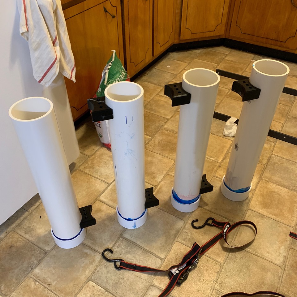
I'm gonna try to make another diagram for this later, but basically the idea is to put epoxy glue on one side of each spacer, place the tanks side by side with spacers in between, and use racheting truck straps to squeeze the whole assembly together. Placing this collection on its side, on the floor, will ensure that they form a straight line. The top spacers should each be glued to the tank on their right, and the bottom spacers glued to the tank on their left. (See photo)
With this section completed, you'll have a freestanding set of modular tanks. They can be separated to make it easier to fill/empty/clean individual tanks but will self-align when you place them in a close row.
Constructing the frame
This section will go much the opposite way of the previous. There won't be more gluing but there will be a bunch of drilling. Six holes per stage, in fact, with most of them being drilled in increments to help maintain accuracy.
You'll be drilling these holes in the grey PVC bars. The holes will need to be drilled in the following locations, relative to the end of bar, and centered with respect to the width of the bar:
- 2 1/4"
- 8 1/4"
- 11 1/4"
- 12"
- 14"
- 35 1/4" (Note! This hole will be a different size!!)
The important part is to try and get these hole positions consistent across all the bars. Start by marking the hole positions with a sharpie and a measuring tape. After the first marked bar, you can mark each one next to the previous one as a visual guide to make sure they're in the same spot.
To make it easier to mark the center line of the bar, you can use a center finder, which is simple to 3D print but also simple to make with a piece of wood and a drill. The Amazon link is there mainly as a lazy way to show what a center-finder looks like... Personally I think it's more fun to make one yourself!
Most of the holes will have a final diameter of 3/8". I recommend drilling these in three stages because the PVC material is quite sturdy. The last hole will have the final diameter of a #7 drill bit because you're going to "tap" this hole to add a thread. You can also use the #7 drill bit as the pilot hole for the larger holes.
Similar to drilling the rollers, you'll want to take care to get these holes as perpendicular as you can to the surface. You'll also want to be careful that the drill doesn't catch on the plastic and swing the whole bar around like a medieval flail!
Once you have drilled the holes you can now tap the small hole at the end of each bar. You'll need a tap wrench and a tap sized for a 1/4"-20 thread. Tapping like this is generally done by hand, even though you will certainly be tempted to chuck the tap into your drill. This is a very good way to break the fragile tap and get it stuck inside the board. Take your time with this step, and for every three full turns you should turn backwards once to let the cut plastic exit the hole.
Finally you can attach the 3D-printed parts to the bar. This will be the "topmount" and the round "spacer" parts. Notice how these parts also have a hole that is about the same size as the holes you just drilled? You'll be bolting these on to the bar using the 3/8" bolts and nuts. The "topmount" should attach to the third hole from the top (the small hole is on the bottom), and the spacer should be on the second hole from the bottom, or the bottom-most of the large holes.
TODO: put diagram here
Next take a 2" x 1/4"-20 bolt and thread it into the small hole of each bar. The head of the bolt should be on the back of the bar. Next slide one of the rollers onto this bolt as an axle, and use a nylon lock nut to secure it. Don't tighten the nut all the way, just enough for the nut to stay on the bolt. It has a nylon insert that will keep it firmly attached to the bolt.
On the topmount part, next add two more 2" bolts to act as axles for rollers. The holes are large enough for the bolts to be inserted, but small enough that the threads will "bite" into the plastic. Hold the roller between the two mount holes, and turn the bolt so that it threads into the part. Don't over tighten this, as that could break the plastic part. The roller should be able to spin freely on the axle.
Now, put each of your assembled stage columns into a tank. The round spacer should slide neatly into the tank and the top mount should sit on the top of the tank like a lid. Put the tanks next to each other. Take your two punched flat bars and align them with the top two holes of each bar. With the spacer blocks properly attacked the tanks, you should find that the holes in the plastic bars align nicely with the holes in the steel bar, with 8 "spaces" from one column to the next. You have now built the frame of the processor.
Mounting the motor
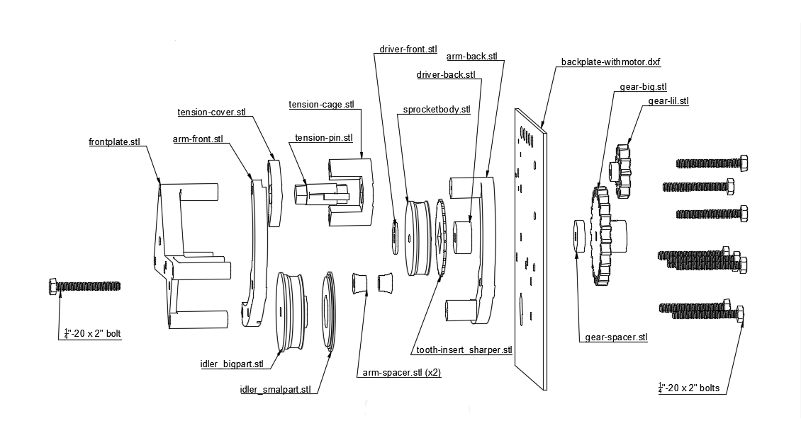
This section covers a recently-developed change to the SLP design. Where previously a salvaged projector sprocket and clamping roller were used (and certainly still could be, if you wish to adapt one), the design now includes files to 3D print a sprocket mechanism to pull the film through the tanks.
In addition to the printed parts, you'll need a wide rubber band, a few nuts and bolts, a certain DC motor, and a small metal drive shaft. You'll also need an 8" by 8" by 1/8" thick sheet of plywood, or really any material you are able to drill holes in that will also be rigid. This is where access to a 40W laser cutter would come in handy; but you can also simply print out the template, paste it to the board, and transfer the holes with a cordless drill. The curved slot on the template may be impractical to drill by hand, but it's only there to make room for a bolt. You can saw out the section of the board surrounding the slot, provided the other holes remain intact.
Next it's time to build the takeup mechanism. Far simpler in comparison to the film driver; the takeup consists of a motor, 3 printed parts, 3 magnets, a washer, and a 2-inch set screw. You'll also need an adhesive, which can be superglue or the plastic epoxy previously used to connect the spacer blocks to the tanks. (In retrospect, maybe too many things are called spacers...)
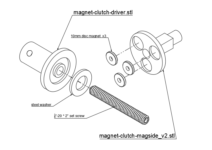
Once the glues/epoxies have dried, you can slip the magnet side onto the driver side with the magnets facing the washer. The magnet side should turn with the driver side and not spin loosely on its own, but also not require a lot of force to turn. This will allow the film to be rolled up when there is slack, and prevent pulling hard on the film when there is not slack.